Assumptions:
As the site is close to the water and near a city access for supplying fingerlings is via a wharf. Fingerlings are to be transported by tanker truck to a tending vessel containing holding tanks specifically designed for this specific purpose.
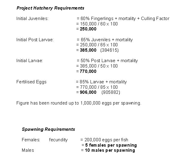
A culling factor of 25% has been added to the 120,000 fingerlings required each month bring the total production to 150,000 fingerlings per month.
In this example, cost cutting on hatchery components would not be a commercially viable option due to the high efficiency requirements. The example of a continuous batch culture hatchery is probably the future in high demand aquaculture production methods such as RAS Systems. However, this design is a direct comparison to the owner operator multi-function design.
"Seahorses for sea-courses".
Example Hatchery Design Criteria
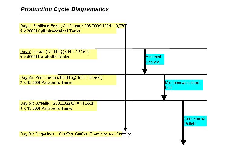
Biological Hatchery Output

Females are to be pre checked for eggs at stage II by catheter sampling.
Male’s sperm to be examined for motility and obvious signs of blood in the fluid.
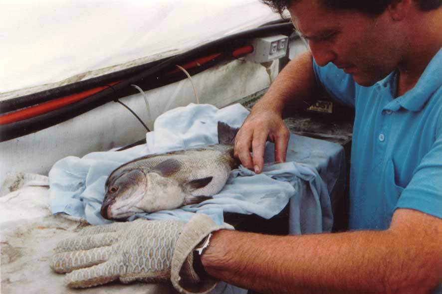
Egg Sampling silver perch
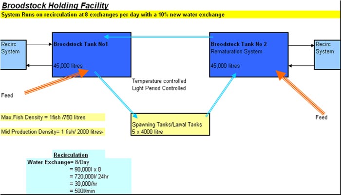
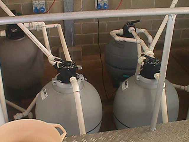
The above design represents two stand alone broodstock systems utilising a controlled environment where careful broodstock management can be carried out. It is so vital that all aspect for the well being of these fish be constantly monitored and controlled.
Water Budget & Inflow Pump Requirements
The project requires 5,800 litres per min or 352,371 litres per hour at maximum demand. This figure equates to 8.64 megalitres per maximum demand 24-hour period.
In this design the main inlet pump system will be a double pump system designed to pump at 3000 litres per min each pump. The pumps will deliver 6000 litres per min at maximum demand into a 36 megalitre holding pond that is 40m x 300m x 3 meters deep. This allows for a standby supply of approximately 4 days at maximum demand as well as cleaning and maintenance times during the times of less demand. There is a standby generator housed with the pumps for electrical blackouts, which is separate from the main standby hatchery generator. The “header” pond is lined and has a discharge to waste sump as well as individual outlet pumps and sand filters supplying each individual stage as outlined in the water budget and operational plan view information.
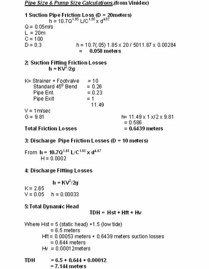
The inflow system utilises 300mm I.D. PVC pipe for suction and discharge. The suction side is 20m in length and is mounted on a 1 meter concrete platform on the bottom of the bay approximately 3 meters below mean low tide. The intakes are screened and have foot valves installed. No major wave action has been recorded at this location.
The inflow pipe and pump calculations have been made with the design assumption that the maximum inflow velocity is 1m/sec. The pipe size and statistics are; 300ml/3000l/1m V/sec.
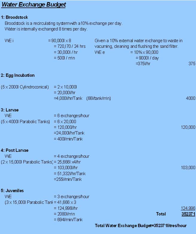
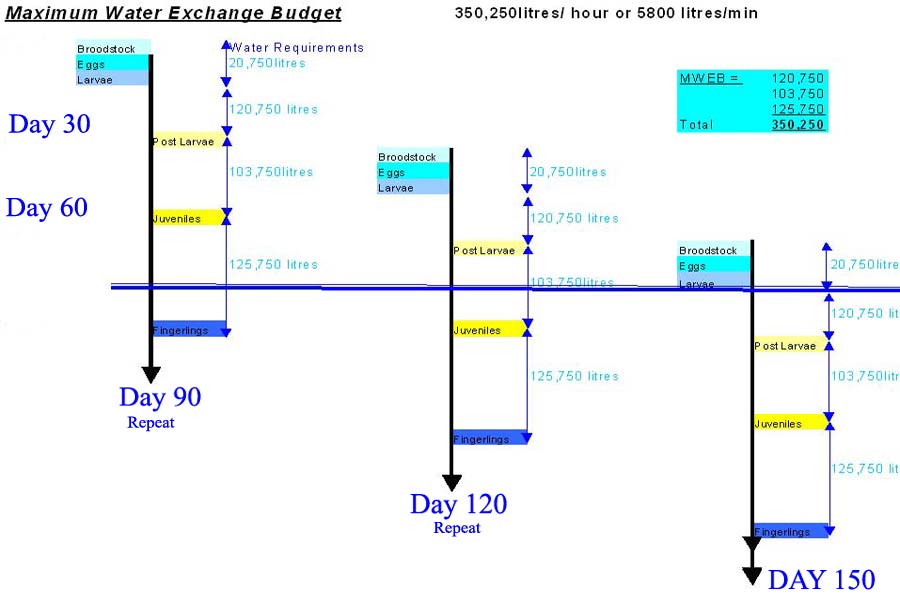
From the diagram the maximum water exchange appears to be 350,250 litres. But due to the production cycle all aspects may be in operation by the third month therefore the maximum water demand is the total sum of the stages which equals 352,371 litres per hour or 5800 litres per minute.
Intake & Water Flow Diagram
The sand filters and other filtration devices used for spawning and larval water supply would be designed to remove particles down to 2 microns.
Post larvae and juvenile stages would be filtered to approximately 50 microns.

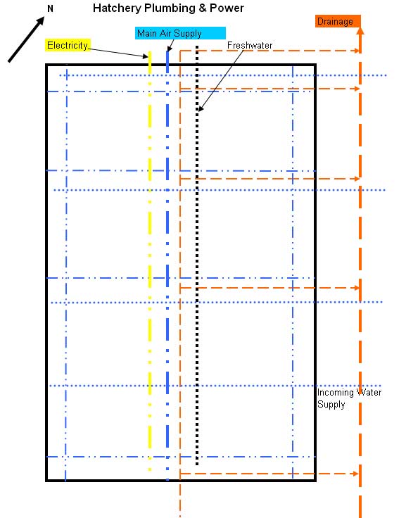
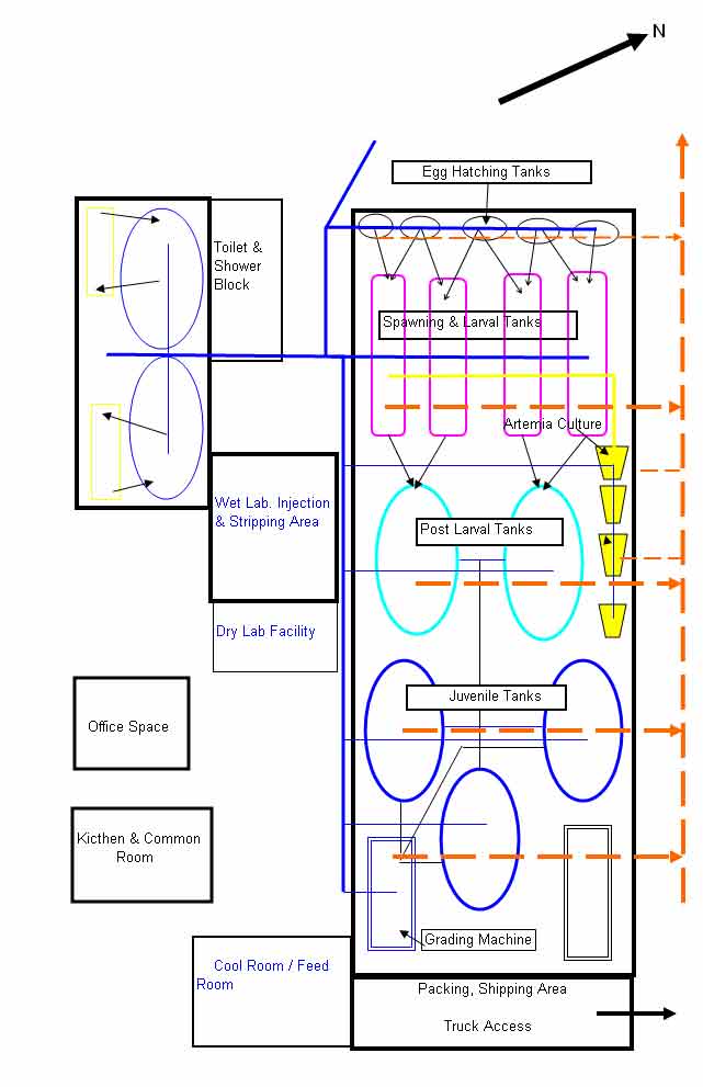
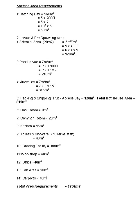
Design Summary
The hatchery building will consist of a prefabricated plastic greenhouse. The dimensions are 45 meters x 20 meters. Gousset 1990 describes a greenhouse as “$10/m2 with significant ability to accumulate solar energy which is transferable into the culture water”. The roof consists of three layers of semi “opaque” white plastic. The extra layer (normally have two) is to increase the thermal co-efficient. The design is anticipated to reduce overall heating costs. The tanks are to be heated with 3-kilowatt ceramic immersion heaters as required during the 4-month lower temperature period. It is anticipated that the sides will need to be lifted during the warmer months to assist cooling. All heaters are to be thermostatically controlled.
All power is via hanging and supported cables. All power in the wet areas is earth leakage protected which is to be tested every 2 weeks. (McConkey & Ward 1985) Alarm security is to be installed for power failure. The hatchery generator will be designed to self-start after a period of 90 seconds and fuel tanks sufficient for 12 hours. The main pump generator is not self-starting as these pumps require inspection prior to powering up.
All the air lines are located overhead and fixed to supply the various stages. All incoming pipe will be 100mm and reduced as per the individual requirements. The blower system is a double system with 2 x 300 litres/min 3 phase commercial blowers.
The project requires two, 3 phase main inlet water pumps that deliver 3000 litres per minute at a velocity of 1 meter per second through 300mm pipe. The suction side pipe length is 20 meters and the delivery side is 10 meters. The use of the large header pond is designed to minimise production crashes due to pump failure. Electric pumps supplying the hatchery are to be of a design that allows for quick replacement in case of failure and replacement pumps should be kept on standby.
From the Hatchery Floor Plan it is anticipated that plumbing connections between tank stages will be portable and not in-line. When not in use the hoses will be stored in fresh water and routinely chlorinated. Stock is not to be handled on mass but is to be flushed through to each new stage.
Provision has been made for sophisticated electronic grading machines with variable sizing and staging to facilitate quick stress-less removal and transportation.
The floor of the hatchery will be concrete with a 1 in 100 fall to the centre drain which will pick up the main drain on the outside of the building. Due to the high turnover of flow to waste, all the hatchery tanks will be permanently connected to the waste side via plumbing set in the concrete floor, draining to the main outside drain. The central open drain will be to aid in cleaning of the area and for portable additions as required. Maintenance schedules should be set up to periodically remove fouling from the drainage system.
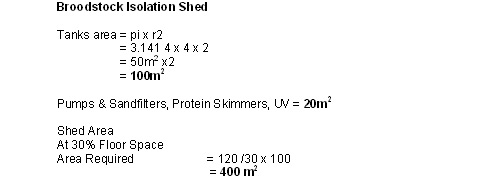
The Broodstock Holding Facility will be a prefabricated steel shed 10m x 40m x 4.5m. The facility would be spray lined with foam for insulation with photo period, ventilation and temperature control. The recirculation and filtration equipment will be housed in a separate but adjoining room to help facilitate noise reduction and good husbandry technique both for the fish and the operators.
The brine shrimp hatching tubes are portable devices for use where and as required. Drainage of brine tubes is to the central drain and rinsing is from the overhead fresh water line. The facility is connected to town water which runs overhead and adjoins the saltwater, power and air systems.
Drainage is to 2 hectares of sedimentation pondage designed to reduce suspended solids and nutrients to as per required in the State Authority Permit. The design of the ponds allows for significant reduction in velocity and the use of nutrient stripping vegetation in the second pond. The exit point is 2 kilometres from the inlet. Aeration will be added both through gravity fall of open drains and demand devices in the ponds for low oxygen situations.

No costing has been entered into in this design but from personal experience cheap is not the best alternative in hatchery construction of this nature. In the above design the 300ml intake would be high-pressure grade PVC pipe as would be the air piping system. Piping in a saltwater hatchery is not the place to cut corners as the overall operational (profitable) life relies on piping functions. If they fail during production runs then, more than likely, a production failure will follow.
The plastic hothouses have proven to be very efficient for hatchery work as they add heat to the system and can be cooled simply by raising the sides thus saving power. Hothouses are relatively cheap and the plastic roof linings last about 8 years so their use in aquaculture will grow as has been the example with agriculture.
This hatchery design article is a summary example covering some of the significant areas needing assessment prior to construction. Costing is another factor where many savings can be made and should be pursued with component suppliers. All of the above factors will require considerable thought and development in consideration of the particular site. Time wasted on design thought, at this time in the project development, will be money saved during construction and operational life span.
Reference Section
Huguenin, J.E. & Colt, J.. Design & Operating Guide For Aquaculture Seawater Systems Second Edition 2002 Elsevier ISBN 0-444-50577-6
Timmons, M. B. & Losordo, T.M. Edit. 2000. Aquaculture Water Reuse Systems:
Engineering Design & Management. Elsevier Pub. ISBN 0-444-89585-x
Berka, R. 1986. The transport of live fish. A Review.
Gousset, B. 1990. European Eel (Anguilla anguilla L.) Farming Technologies in
Europe and in Japan: Application of a Comparative Analysis
Lucchetti & Gray 1988. R 7.1. Water Reuse Systems: A review of principal
components. The Progressive Fish Culturist. Vol. 50:1-6, pp 1-6
Onga Pumps Manual 1991 R4.5
McConkey & Ward 1985 Electrical Low Voltage Systems R3.2
Vinidex The Water Supply Manual For PVC Pipe Systems R-4.4